
An overview of pressure vessels
Definition of pressure tank : It is a container designed to hold gas or liquids at a pressure completely different from the ambient pressure.
Made in the workshop | Based on the type of construction
| Types of classification of pressure vessels
|
Made on site | ||
پرجی | ||
Joshi | ||
forge | ||
casting pressure | ||
Multi-layer pressure tank | ||
steel | According to the material
| |
cast iron | ||
Aluminium | ||
internal pressure | According to pressure | |
external pressure | ||
Direct flame | Based on the heating method | |
Indirect flame | ||
Cylindrical | Based on construction geometry | |
Spherical | ||
conical | ||
Horizontal | Based on placement direction | |
vertical | ||
Inclined | ||
proven | Based on installation | |
mobile | ||
thin wall | Based on thickness | |
thick wall |
tank body : استوانه ای یا کروی | اجزای مخزن تحت فشار |
کلگی های مخزن : تخت،بیضوی،سهموی،نیمه کروی FLAT,ELLIP,TORI,HEMI | |
مهارها : پایه،قلاب،دامنه،سدل LEG,LUG,SKIRT,SADDLE | |
نازل ها و دریچه آدم رو |
استانداردها و کدهای مخازن تحت فشار:
کد: کدها در واقع چیزی جز مجموعه ای از قوانین طراحی ، ساخت ، نصب ، بازرسی و آزمایش کارخانه ها و تجهیزات فرآیند صنعتی نیستند
Standard : شامل مجموعه ای از قوانین است که توسط افراد حرفه ای برای طراحی ، ساخت و یکپارچگی اجزاء تحت فشار تهیه شده است.
کد های رایج دنیا برای مخازن تحت فشار
| کشور | نام سازمان | مخفف | کد(ها) |
| آمریکا | American Society of Mechanical Engineers | ASME | ASME VIII |
| India | Bureau of Indian Standards | IS | IS 2825 |
| Canada | Canadian Standard Association | CSA | CSA B51 |
| Europe | Committee of European Normalisation | IN OR CEN | EN13445 |
| Great Britain | British Standard Institute | BS OR BSI | BS5500 |
| Germany | Deustche Institute of Normalising | FROM | AD2000 |
| Japan | Japanese Industrial Standardisation Committee | JIS OR JISC | JIS B 8243 |
| the world | Organisation for Industrial Standards | ISO | ISO 16528 |
The design of pressure vessels is generally done based on the considerations of the desired services, most of these services are as follows:
- Cyclic Service: Fatigue
- Lethal Service
- Vibration Service
- Shock Service; Thermal or Impulse loading
- Low Temperature Service
- Cryogenic
- High Temperature Service
- Creep
- Creep –Fatigue
- Corrosion Service
- Contents: The contents of the vessel may require
special design considerations and/or material
selection. The following is a list of some of these
special services;
- Hydrogen Service
- Wet H2S Service (Sour Water)
- Caustic Service
- Ammonia Service
- Chloride Service
- Amine Service
- Sulfuric Acid
- Hydrochloric Acid
- Hydrofluoric Acid
- Polythionic Acid
- Types of Hydrogen Service Failures;
- SSC: Sulfide Stress Cracking
- ASSC: Alkaline Sulfide Stress
Cracking
- SZC: Soft Zone Cracking
- HIC: Hydrogen Induced Cracking
- SOHIC: Stress Oriented HIC
- SCC: Stress Corrosion Cracking
- GHSC: Galvanic Hydrogen Stress Cracking
- EC: Environmental Cracking
- Types of Stress Corrosion Cracking (SCC);
- Chloride
- Polythionic
- Caustic
- MY/DEA
- Sulfide
- Ammonia
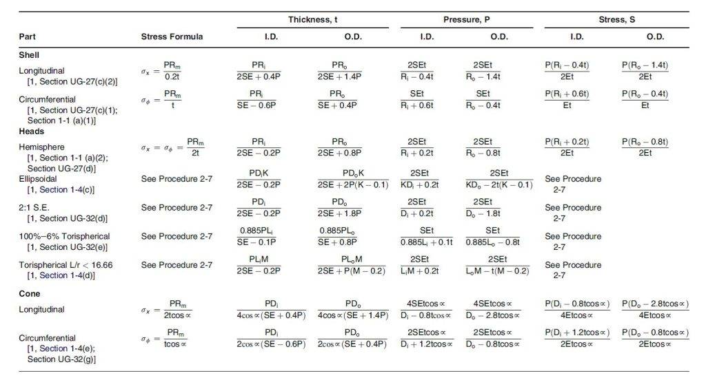
Summary of pressure vessel design formulas
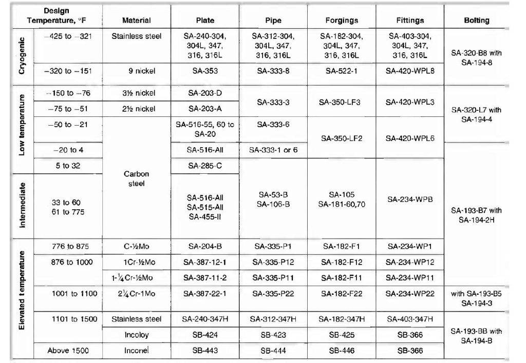
A quick guide to using materials in different services
Notes on the standard ASME
استاندارد ASME به 12 The season is divided:
| Chapter number | Chapter name |
| 1 | RULES FOR CONSTRUCTION OF POWER BOILERS |
| 2 | MATERIALS |
| 3 | Rules for Construction of Nuclear Facility Components |
| 4 | Rules for Construction of Heating Boilers |
| 5 | Nondestructive Examination |
| 6 | Recommended Rules for the Care and Operation of Heating Boilers |
| 7 | Recommended Guidelines for the Care of Power Boilers |
| 8 | Rules for Construction of Pressure Vessels |
| 9 | Welding, Brazing, and Fusing Qualifications |
| 10 | Fiber-Reinforced Plastic Pressure Vessels |
| 11 | Rules for Inservice Inspection of Nuclear Power Plant Components |
| 12 | Rules for Construction and Continued Service of Transport Tanks |
- Chapters 2, 5, 8, 9, 12 are related to pressure vessels
| Chapter number | Title | subset |
| 2 | material | Part A مشخصات فنی مواد آهنی |
| Part B مشخصات فنی مواد غیر آهنی | ||
| PART Cمشخصات فنی الکترودها و سیم جوشها | ||
| Part D ویزگی ها | ||
| 5 | Non-destructive tests | |
| 8 | Construction of pressure vessels | Division 1 |
| Division 2 | ||
| Division 3 | ||
| 9 | Welding and soldering | |
| 12 | Construction of transport tanks | |
- Subsets of the eighth chapter – the part 1
| Subsection A | Part UG | General |
| Subsection B | Part UW | Manufacturing method by welding |
| Part UF | Forging manufacturing method | |
| Part UB | Soldering manufacturing method | |
| Subsection C | Part UCS | Made with iron materials |
| Part UNF | Made with non-ferrous materials | |
| Part of the EAR | ساخت با مواد الیاژی | |
| UCI Part | Made with cast iron | |
| Part UCL | One-piece coated sheets | |
| Part UCD | ||
| Part UHT | Made with heat treated materials | |
| ULW part | ||
| Part ULT | Low temperature service | |
| Part UHX | Heat Exchangers | |
| Part UIG |
- Welding connection classification
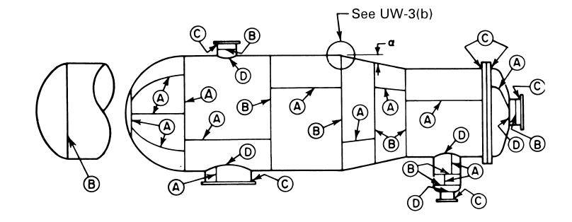
| the name of the group | Attributes |
| A | Longitudinal welds in the body and nozzles, all welds located in the spherical or flat flange, peripheral welds connected to the spherical flange that is connected to the nozzle or body |
| B | Peripheral welds in the body and nozzle, peripheral welds connected to the lens of the given form( Except spherical ) که به بدنه یا نازل وصل شود |
| C | جوش فلنج ، تیوب شیت یا عدسی تخت به بدنه ، عدسی یا نازل |
| D | جوش نازل ها به بدنه ،عدسی ها و نازل ها |
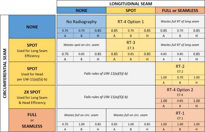
جدول راندمان جوش ها
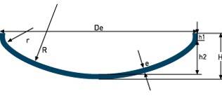
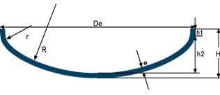
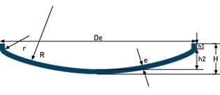
انواع کلگی (HEADS )
| شکل عدسی | نام عدسی | مشخصات | |
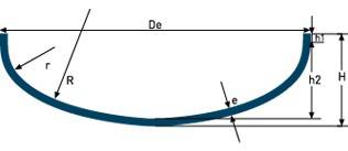 | Elliptical Head (NF E 81-103) | R≈ 0.856De r≈ 0.183De h1≥ 3e h2= Di/3.8 H= h2+h1+e V(h2)≈ (Di.1,06)².0,466h2 | |
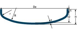 | G.R.C. (NF E 81-102) | R= Of r= 0.1De h1≥ 3.5e h2= 0.1935De-0.455e H= h2+h1+e Dd= 1.11De+1.85h1 V(h2)≈ 0.1(Di)³ | |
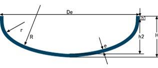 | Ellipsoidal head ASME | Form 1,9:1 Di = Da – 2 x s r1 = Di / 1,16 r2 = Di / 5,39 h1 = gem. NF E81-103 h2 = Di / 3,8 h3 = h1 + h2 | Form 2:1 R≈ 0.9De |
 | Flanged & Dished (ASME) | R= De r= 0.06De h2= R-√((R-r)²-(Di/2-r)²) H= h2+h1+e V(h2)≈ (Di/25,4)³.0,0013 | |
 | Hemispherical head | R=0.5Di CALOTA + SECTORS V≈0,2618Say³ | |
 | The basket book (FROM 28013)
| R= 0.8De r= 0.154De h1≥ 3e h2= 0.255De-0.635e H= h2+h1+e Dd= 1.16De+ 2h1 V(h2)= 0.1298(Di)³ | |
 | Beater (FROM 28011)
| R= Of r= R/10 h1≥ 3,5e h2= 0.1935De-0.455e H= h2+h1+e Dd= 1.11De+1.85h1 V(h2)= 0.1(Di)³ | |
 | High Crown Flanged & Dished (ASME)
| R= 0.8De r= 0.06De h2= R-√((R-r)²-(Di/2-r)²) H= h2+h1+e V(h2)≈ (Di/25,4)³.0,0016 | |
 | 80-10 Flanged & Dished (ASME) | R= 0.8De r=0.1De h2= R-√((R-r)²-(Di/2-r)²) H= h2+h1+e V(h2)≈ (Di/25,4)³.0,0019
| |
 | M.R.C. (NF E 81-104) Dished head | R= Of h2= R-√((R-r)²-(Di/2-r)²) H= h2+h1+e V(h2)≈ (De+r)².0,42h2 | |
MRC NF E 81 104 Dished head | R= Of h2= R-√((R-r)²-(Di/2-r)²) H= h2+h1+e V(h2)≈ (De+r)².0,42h2 | ||
نکات مربوط به ساخت ، بازرسی ( FABRICATION):
cutting: درصورت برش ورق با اکسیژن یا قوس، اکسیدهای ناشی از برش باید به روش مکانیکی برطرف شود اگر سطح برشکاری شده برای جوشکاری استفاده نمیشود فقط ایجاد سطح صاف کافی است UG – 76
Out-of-round tolerance in internal pressure tank: The difference between the maximum and minimum internal diameter should not exceed one percent of the nominal diameter UG - 80
Out-of-round tolerance for collies : For parabolic, conical, spherical and elliptical UG cones – 81
- The deviation of the inner part of the lens should be within the range 4/5% diameter and 8/5 % The diameter is located
- The KNUCKLE radius should not be less than the specified value
- Out of roundness of SKIRT is allowed a maximum of 1% diameter
Hydrostatic test : class UG- 99 Hydrostatic test pressure 1.3 equal to MAWP times the ratio ( Stress at test temperature to stress at design temperature) It is used for steel, usually this ratio is considered one. Inspection of the tank should be divided into test pressure 1.3 انجام شود.برای جلوگیری از خطر شکست ترد دمای آزمون بهتر است 17 °C above MDMT and from 48 The degree should not be higher.
Pressure control devices ( Safety valve or safety valve …): تنظیم فشار سوپاپ اطمینان در صورت استفاده از یک سوپاپ نباید از MAWP بیشتر باشددر صورت استفاده از بیش از یک سوپاپ فشار سوپاپ اول کمتر یا مساوی MAWP و سوپاپ دوم در فشاری بالاتر از MAWP ( Maximum 105 Percentage of MAWP) be set
Division of reservoirs in ASME بر اساس محدودیت های سرویس مورد استفاده
- Deadly service
- low temperature
- Steam
- Direct flame
| Service type | comments |
| deadly (LETHAL) | · تمامی جوشها باید رادیوگرافی شوند · مخازن با فولاد کربن استیل و کم الیاژ باید تنش زدایی شوند · همه جوشهای دسته A باید از نوع 1 to be · همه جوشهای دسته B,C must be of type 1 Or 2 to be · جوشهای دسته D باید نفوذی کامل باشند |
| LOW TEMPERATURE | · همه جوشهای دسته A باید از نوع 1 to be · همه جوشهای دسته B باید از نوع 1 Or 2 to be · جوشهای دسته D C, Must be full penetration |
Weld design acc ASME :
- The dimensions and shape of the edges should be such that full penetration and complete melting are done
- The length of the taper should not be less than three times the trim
- Taper is done when the thickness of the trim is from 3 desire or 0.25 The percentage of sheet thickness is less( Each is smaller ) be
- Both welding and cutting are acceptable for taper
- The distance between two longitudinal welding lines in two adjacent bodies from 5 not less than the thickness of the thicker sheet
Radiography and non-destructive tests:
- Regarding welding efficiency ( JOINT EFFICIENCY ) Refer to the weld efficiency table above. Refer to the relevant table on this site regarding the criteria for the acceptance of welds in radiography.
- It is allowed to use ultrasonic method instead of radiography in pressure tanks
- If according to the design, local radiography (SPOT) برای کل مخزن در نظر گرفته شود برای جوشهای لب به لب دسته B,C
در نازل های حداکثر 10اینچ و حداکثر ضخامت 29 میلیمتر به رادیوگرافی نیست
- درصورت رادیوگرافی موضعی ،در هر مخزن به ازای هر 15 متر خط جوش حداقل 6 اینچ رادیوگرافی انجام شود
- به ازای هر جوشکار یا اپراتور یک 6 اینچی باید رادیوگرافی شود
تلرانس عدم همترازی در مونتاژ ( HI-LO)
| ضخامت /mm | جوشهای A | جوشهای B,C,D |
| until the 13 و13 | ¼ ضخامت | ¼ ضخامت |
| بیش از 13 until the 19 And 19 | 3mm | ¼ ضخامت |
| بیش از 19 until the 38 And 38 | 3mm | 5mm |
| بیش از 38 until the 51 And 51 | 3mm | 1/8 t |
| بالای 51 | کمتر از 1/16 t یا 10 mm | کمتر از 1/8t یا 19 mm |
حداکثر گرده جوش :
| ضخامت /mm | جوشهای دسته B,C لب به لب | سایر جوشها |
| until the 2.4 | 2.4 | 0.8 |
| بیش از 2.4 until the 4.8 | 3.2 | 1.6 |
| بیش از 4.8 until the 13 | 4 | 2.4 |
| بیش از 13 until the 25 | 4.8 | 2.4 |
| بیش از 25 until the 51 | 5 | 3.2 |
| بیش از 51 until the 76 | 6 | 4 |
| بیش از 76 until the 102 | 6 | 6 |
| بیش از 102 until the 127 | 6 | 6 |
| بیش از 127 | 8 | 8 |
عملیات حرارتی تنش زداییPWHT
PWHT can be used to reduce residual stresses, as a method to control hardness or even to increase the strength of materials. Doing the stress relief process incorrectly can lead to weld failure, more cracking, and increased susceptibility to brittle fracture..
There are different types of PWHT, the two most common types of which are: :
- POST HEATING:
Hydrogen cracking (HIC) It often occurs when a large amount of ambient hydrogen penetrates the material during welding. با گرم کردن ماده پس از جوشکاری ، می توان هیدروژن را از منطقه جوش داده شده متفرق کرد ، بنابراین از HIC جلوگیری می شود. این فرایند به عنوان پس گرمایش شناخته می شود و باید بلافاصله پس از اتمام جوشکاری آغاز شود. به جای اینکه اجازه داده شود تا خنک شود ، بسته به نوع و ضخامت مواد لازم است تا درجه حرارت مشخص شود. بسته به ضخامت ماده باید چند ساعت در این دما نگه داشته شود.
- تنش زدایی STRESS Relieving :
فرآیند جوشکاری می تواندمقادیر زیادی تنش باقیمانده را در ماده ایجاد کند ، که می تواند منجر به افزایش پتانسیل خوردگی تنش و ترک خوردگی ناشی از هیدروژن شود. از PWHT می توان برای از بین بردن این تنشهای باقیمانده و کاهش این پتانسیل استفاده کرد. این فرایند شامل گرم كردن مواد تا دمای خاص و سپس سردکردن تدریجی آنها است.
- دمای کوره نباید در هنگام قرارگرفتن مخزن در داخل ان نباید از 425 درجه سانتی گراد بیشتر باشد
- بالای 425 درجه آهنگ گرم کردن نباید از 222 درجه در ساعت به ازای ضخامت قطعه بیشتر باشد
- در حین گرم کردن تغییرات دمایی در فواصل 1.6 متری از 139 درجه بیشتر نشود
- در زمان نگهداشت اختلاف حداکثر دما و حداقل دما کوره در نقاط مختلف مخزن از 83 درجه تجاوز نکند
- محیط کوره از نظر اکسیداسیون بیش از حد باید کنترل گردد
- بالای 425 درجه آهنگ سرمایش از 280 درجه بر ساعت به ازای حداکثر ضخامت فلز بیشتر نشود
- اهنگ گرمایش و سرمایش به طور کلی از 56 درجه بر ساعت کمتر نباشد
- در صورت به رفتن فولاد با چند نوع P NUMBER از دمای بالاتر استفاده گردد
- درصورت انجام تعمیرات برای 1,2,3 تا ضخامت 38 میل بعد از عملیات حرارتی نیاز ه عملیات حرارتی مجدد نیست